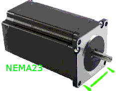
This article will cause some confusion for most readers, as it covers Standards, electromechanics, and Chip-maker rhetoric.
First of all, one will generally see a motor listed with minimal specifications, but note the NEMA number only really describes the physical size and has absolutely nothing to do with the holding-torque rating.
 |
|
For most motion control platforms, we want to minimize the diameter of the motor as much as possible, and prefer a longer narrower body of the same torque rating over a higher NEMA size. This choice usually significantly lowers the angular momentum of the motor itself, and allows faster control response with lower step position error.
Micro-stepping is a great technology for some applications, but generally users do not understand when the technology should be avoided. These drivers usually should never be used with parallel stepper configurations unless it is in simple half-step mode. Additionally, even in half-step mode we lose nearly 30% of the torque rating from the motor. Thus, when micro-stepping into 1/4 mode or higher we sacrifice the ability to parallel motors as the chip can't know where the drive power is being used, and even stacking the drivers will not recover the motor torque lost to the driving trick. Note, most motor manufacturers optimistically guarantee the step position error within 5%, and often exclude shaft movement in a no-pre-loaded bearing setup. There is little the driver chips can do to recover precision, as monitoring the current flow cannot represent the actual position of the shaft. In general, a high-holding-torque 0.9' degree motor will be slower than the equivalent 1.8' degree version, but offers twice the resolution with half the positional errors.

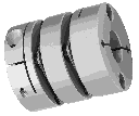
 The double-diaphragm-coupling is the best for smaller lead-screw based machines, as it allows motor alignment error without binding or prematurely damaging the motor bearings. Accordingly, one should avoid motors with lead screws turned onto the motor shaft itself, and allow one end of the lead screw to "float" in a spring tensioned bearing. This should mean only one end of the lead screw is anchored to the machine itself, and changes in temperature will not cause localized binding/bowing or uneven wearing of the threads.
Note, many machines will often use a tensioned Kevlar toothed-belt reduction-drive to increase toque and precision. Often this mechanical "fuse" can prove useful in higher power drive systems where operator errors are common.
