This article covers how to determine if the PCB needs cleaned, repaired, or firmware updated. Some notes are also provided based on some of our groups experiences with various components under analysis conditions.
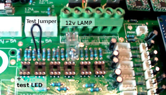
A few components are required to load test each power mosfet, and these can be easily obtained though local automotive-parts retailers. A Test-jumper made from copper wire or a cut paper-clip, and a 12vDC 20W incandescent lamp bulb. Optionally, a 3mm test LED can also be used to test the logic levels.
- Shutdown the OS, and Unplug the power supply
- Insert Lamp into the green Amphenol terminal block (note these plugs have a minimum wire size requirement)
- tighten terminal block screws
- Insert Test-jumper across opto pin 4 and pin 5 to turn on a specific lamp output power mosfet under test
- Optionally insert standard 3mm LED into pin 1(+) and pin 2(-) of the optical coupler logic input you wish to debug
- Plug back in system
- After Boot up, enable power to the motherboard to see if light turns on
- Run firmware test to see if LED is on when logic is high (if nothing happens, check if the LED inserted backwards)
Possible test results:
- If LAMP stays off while test-jumper is inserted the 12v Fuses (did all 5 power-bus LEDS light?) or MOSFET may need replaced
- If LAMP stays on when test-jumper is removed the PCB may have short, or MOSFET may need replaced
- If LED is always off, it could mean the LED is inserted backwards, firmware has a bug, and or the Arduino IO pin is damaged
- if LED turns ON/OFF as expected and Lamp Test-jumper confirms FET is OK, than the opto-coupler may need replaced
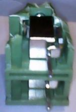
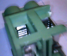
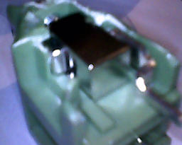
Notes about Amphenol terminal blocks:
We feel it may be necessary to explain why testing voltages across terminal screws may not always show the true output state sometimes. These photos show that high-current contact clamps may not be in full contact with the conductor surface unless tightened onto a conductor wire of sufficient gauge.