
Hi,
first off, thanks for the great motherboard and the distribution, this is just awesome!
I started connecting the motherboard to the power supply but run into a snag on Step7 where it says I should connect 2 2x2 12V connectors for additional power. As it turns out, the power supply I have doesn't have 2 2x2 connectors, but it does have a single 2x4 connector which can be split into two separate 2x2 connectors:
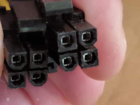
Unfortunately, only one of those two fits into the motherboard (the left one in the picture above). The other one has the arrangement of the square and U shaped pins reversed and doesn't fit.
So the question is: What should I do with the second connector?
Leave the second one unconnected?
Take a knife to the right plug in the picture above and make it fit?
Thanks in advance,
Markus
Thanks for the photo =)
That is not a normal 4+4 power connector, but rather an EPS 8-pin (EPS12V) gender-key for dual-CPU boards... that was split into two 4-pin style plugs. This is weird as only one of the split eps8 sides could fit into a gpu card, and suggests the right side key layout is connected to a secondary rail like 12v2.
As long as the left side plug fits, and has the color coded wires like below (note in a 4+4 plug the right side plug's pins would have only rounded off keys)... than you can insert only one side of the Infinity Motherboard 16A inputs. Note that since the left side eps8 pins 5/6 (14A max) are usually connected internally to the 12v1 rail like the 24pin ATX 12v1 (12A), than the two cables could supply up to 26A max from the 12v1 rail.
However, the supply you mentioned before is rated at 22A for rail 12v1, and thus will limit you to around 19A of stepper-motor (around 5 NEMA17 motors) load before it starts to trip over-current-shutdowns. If this happens, you must reset the supply by shutting down the OS if still running, unplugging the power cord for a minute, and powering the system back on... to try a lower current-setting on the motor-driver-modules.
Hope this helps,
J
knife it is
Thanks for the background and link. Indeed the keying is consistent with a 8-pin ESP plug from above website. According to the description of the 4x4 plug on the same page I should just not plug in the right half of the plug - however, their version of the right half would fit - so I think I'm gonna make my other half fit as well.
I'm not ready to give up on 14A that easily, I have 4 axes to feed ;)
don't try this at home ...
Managed to re-key the second half of the connector without having to provide any DNA samples - always a bonus.
AFAICT all the green LEDs are on - 5 of them if I count correctly.